| Boolean Algebra |
Introduction
Boolean algebra is a type of algebra that is used in the design of (digital) logic circuitry,computer programs such as search engines and in general in analytic reasoning.
It is an arithmetic interpretation of Proposition Logic and is also similar to Set theory.
Boolean algebra was designed by the British mathematician George Boole (1815 - 1864).
Click [ HERE ] for Logic10 , a program that handles Boolean algebra formula's.
Variables and operators
A boolean variable may have the value "true" or "false".For the purpose of arithmetic operations, "true" is represented by "1" and false is represented by "0".
In this article, a boolean variable is denoted by a single character like A,B or C.
A variable stands for a proposition such as "start switch pressed" , "temperature within range",
"counter value = 6" , "John is 10 years old" ....etc.
Note, that a proposition is either true(1) or false(0).
Outside, the sun is shining or not. A switch, or a door, is open or closed.
Boolean Algebra knows 3 basic operations which are AND, OR and NOT
Using these operators, Boolean variables may be combined into formula's for more complex propositions.
AND
The operator for AND is "." (point)| A | B | A.B |
| 0 | 0 | 0 |
| 1 | 0 | 0 |
| 0 | 1 | 0 |
| 1 | 1 | 1 |
In an AND family, both the parents must agree to grant the request of a child.
All possible AND operations between 2 variables are listed:
-
0.0 = 0
0.1 = 0
1.0 = 0
1.1 = 1
In electro-mechanics, an AND may be formed by switches in series:
current can flow only if both switches are closed.
In electronics, a circuit that performs an AND function is called an AND gate.
In diode logic, the output voltage is high (1) when all A,B,C inputs are high.
The diodes isolate variables A,B,C.
For AND operations, the associative rule applies: A.(B.C) = (A.B).C
Also the communicative rule applies: A.B = B.A
OR
The operator for OR is "+"| -A- | -B- | -A+B- |
| 0 | 0 | 0 |
| 1 | 0 | 1 |
| 0 | 1 | 1 |
| 1 | 1 | 1 |
In an OR family, only one of the parents must agree to grant the request of a child.
In diode logic, the output is high (1) when at least one of the inputs is high (+12V).
For OR operations, the associative rule applies: A+(B+C) = (A+B)+C
Also the communicative rule applies: A+B = B + A
All possible OR operations between 2 variables are listed:
-
0+0 = 0
0+1 = 1
1+0 = 1
1+1 = 1
In electro-mechanics, an OR operation may be formed by applying switches in parallel:
current may flow if either or both switches are closed.
In electronics, a circuit that performs an OR function is called an OR gate.
NOT
This is the negation of a value.NOT is a unairy operator placed before a variable to negate it's value.
In Boolean algebra, NOT is normally represented by a solid bar on top of the variable, like
Because this top bar is hard to edit, we also use / just before the variable.
So not A = /A =

| -A- | -NOT A- |
| 0 | 1 |
| 1 | 0 |
In electromechanics, an inverse operation takes place when pressing a switch causes it to open,
inhibiting current flow. (supposing that "switch pressed" = "1")
In electronics, a circuit that performs a NOT function is called an INVERTER.
The (Diode-Transistor logic) inverter outputs 0 (0V) when the input is hi (12V).
Note: AND , OR gates are always followed by an inverter to amplify the signals.
Common practice are not AND (NAND) and not OR (NOR) gates.
And gates, Or gates and Inverters are the sole building blocks for digital equipment.
Adders, shift networks, decoders, multiplexers, timing chains, memories:
all are designed using only these three functions.
XOR
AND and OR functions, together with INVERTERS, are combined to build more complex circuitry.The most important function is XOR , "exclusive or" , also called "logical difference" or "half adder" ,
because it is the key function in building adders and counters.
The definition of XOR is : A XOR B = A./B + /A.B
So, an XOR operation between A and B yields true if the values of A and B are unequal.
Note:
for XOR, also the communicative and associative laws hold.
Extra is, that the XOR function is it's own INVERSE: A XOR B XOR B = A
Multiple Variables
AND , OR operations may involve more than 2 variables,The formula A.B.C.D will only yield true (1) if all A,B,C,D are 1.
The formula A+B+C+D will yield true (1) if at least one of A,B,C,D is 1.
The formula A./B.C will be true only if A=1, B=0 (so /B=1) and C=1.
The distributive laws
Boolean algebra knows two distributive laws with operations AND and OR.-
1..........A.(B+C) = A.B + A.C
2..........A + B.C = (A+B).(A+C)
Inconsistent
A Boolean algebra formula is called inconsistent if the result is never true.A simple inconsistency is: A./A
Tautology
A tautology is a proposition (formula) that always yields true.A simple tautology is A + /A
Rules for Reduction
A complex proposition may be simplified in some cases.The redundancy may be squeezed out, which saves circuitry in digital design or simplifies a program.
The reduction rules are
-
1...A + A = A
2...A + A.B = A
3...A . B + A . /B = A
4...A + /A . B = A + B
5...A./B + A./C + BC = A + B.C
6...AB + /AC + BC = AB + /AC
1. follows from definition.
2. Distributive law: A + A.B = A.(1 + B) = A
3. Distributive law: A./B + A.B = A.(/B + B) = A
4. Distributive law 2: A + /AB = (A + /A)(A+B) = 1.(A+B) =A + B
5. will have to wait.
6. AB + /AC + BC = AB +/AC + /ABC + ABC = AB + /AC (rule 2, combine terms 1,4 and also 2,3)
-
A proof is also to generate all possible values of A,B,C and compare the results.
| A | B | C | A.A | A+A | A+B | A.B+A./B | A+/A.B | A./B+A./C+B.C | A+BC |
| 0 | 0 | 0 | 0 | 0 | 0 | 0 | 0 | 0 | 0 |
| 1 | 0 | 0 | 1 | 1 | 1 | 1 | 1 | 1 | 1 |
| 0 | 1 | 0 | 0 | 0 | 1 | 0 | 1 | 0 | 0 |
| 1 | 1 | 0 | 1 | 1 | 1 | 1 | 1 | 1 | 1 |
| 0 | 0 | 1 | 0 | 0 | 0 | 0 | 0 | 0 | 0 |
| 1 | 0 | 1 | 1 | 1 | 1 | 1 | 1 | 1 | 1 |
| 0 | 1 | 1 | 0 | 0 | 1 | 0 | 1 | 1 | 1 |
| 1 | 1 | 1 | 1 | 1 | 1 | 1 | 1 | 1 | 1 |
of Boolean Algebra formula's. But they are no isolated rules.
In fact, there is a better and more universal way so it is better to consider them as examples.
De Morgan's laws
|
1....../A + /B = /(A.B) 2....../A . /B = /(A +B) |
 |
The proof is left to the reader.
De Morgan's laws state, that : an AND for 1's is an OR for 0's and also:
an OR for 1's is an AND for 0's
If a generator is switched on by pressing two switches in series,
only one switch needs to be released to switch the generator off.
Another proof of rule4, using De Morgan's laws:
Examples:
Truth Tables
A Truth Table lists all combinations of variables for which a formula yields "true".A truth Table has the form: A.B.C + D.E.F + G.H.I + ........
The AND combinations are written per row, rows are ORed.
This form is also called the "conjunctive normal form".(CNF)
Generating the truth table of a formula is converting the formula to the CNF form.
Example
In digital equipment, 7 segment displays are often applied to display numbers.A decimal digit needs 4 bits, let these bits be A(bit-0-) , B(bit-1-) , C(bit-2-), D(bit-3).
We build a truth table for the cases where the top segment must be on.
| digit | A | B | C | D |
| 0 | 0 | 0 | 0 | 0 |
| 2 | 0 | 1 | 0 | 0 |
| 3 | 1 | 1 | 0 | 0 |
| 5 | 1 | 0 | 1 | 0 |
| 6 | 0 | 1 | 1 | 0 |
| 7 | 1 | 1 | 1 | 0 |
| 8 | 0 | 0 | 0 | 1 |
| 9 | 1 | 0 | 0 | 1 |
a 0 means that the variable must be "0" (so /A,/B,/C.....)
The first 3 rows of the table are equivalent to /A./B./C./D + /A.B./C./D + A.B./C./D
The table may be reduced by applying the rule A./B + A.B = A.(/B + B) = A
For A, we read all equal bits, B ,/B are a single difference bits.
Rows 1,2 for digits 0,2 differ only in 1 bit, so may be combined to 0x00, where x (here B) is a don't care bit.
Also, for digits 5,7 bit B is the only difference, so these rows may be replaced by 1x10.
Rows for digits 8,9 are similarly combined into x001.
The truth table is now reduced to
| A | B | C | D |
| 0 | x | 0 | 0 |
| 1 | 1 | 0 | 0 |
| 1 | x | 1 | 0 |
| 0 | 1 | 1 | 0 |
| x | 0 | 0 | 1 |
Now comparing rows 2,4 similarly results in eliminating bit C of row 4.
The final truth table becomes:
| A | B | C | D |
| 0 | x | 0 | 0 |
| x | 1 | 0 | 0 |
| 1 | x | 1 | 0 |
| 0 | 1 | x | 0 |
| x | 0 | 0 | 1 |
then complement the result.
Applications
Electro Mechanics
This involves switches and relays, which are used in process automation to apply power to motors,energize magnetic valves to allow liquids to flow, etc.
Switches are manufactured in enormous varieties: normally open, normally closed, momentary, toggle,
large and small....
Let us call the switch "A" and A = 1 means : switch A is pressed.
Then, for contacts 1,2 the logical function is /A, because current is conducted when the switch is not pressed.
Contacts 3,4 perform the function A, because these contacts are closed only if the switch is pressed.
A relay is basically a switch that is energized by a magnet (coil with iron core).
When current flows trhough the coil, the switches are pushed and current may flow through contacts:
5-6 , 9-10 , 13-14.
In de-energized state, current my flow through contacts 3-4 , 7-8, 9-10.
Because all the necessary logical functions are there, it is possible to build a digital computer using only relays.
Bus Stop
Buses for public transportation often have buttons mounted above the passenger seatsfor stops on request.
The buttons are momentary switches. A STOP light should stay on after the passenger releases the button
(it is not necessary to hold the butten until the next bus stop).
So, a 1 bit memory is required to hold the STOP condition.
At the bus stop however, the light must be switched off. The condition "doors open" is convenient to accomplish this.
How would this circuitry look?
R is a relay. D is the doorswitch. D means : doors are open.
Switches and relay are pictured in the de-energized (0) state.
When a passenger presses a button, current flows through the coil and contacts 1,2 of D (if door is closed).
R energizes, so current flows through coil and contacts 5,6 of R (again if door is closed).
When the passenger releases button A or B, the relay keeps energized until the bus stops,
the doors are opened causing contacts 1,2 of D to break and R de-energizes.
When R is energized, contacts 9,10 close and the STOP request lamp lights.
The logic formula for R is : R = (A + B)./D + R./D = (A+B+R)./D
R occurring both left and right of the = sign indicates the memory function.
Electronics
In computers, logic functions are made with electronics, because electronic switches are the fastest available.There are several type of logic circuits, such as DTL (diode transistor logic), TTL (transistor transistor logic),
RTL (resistor transistor logic) and the fastest of all ECL (emitter coupled logic).
All have their specific voltage levels to represent a "0" or a "1".
For TTL, a "0" is 0 ....0.8 Volt and a "1" is any voltage above 2.2Volt (supply power is 5 Volt).
Below is pictured a simple DTL 2 input NAND gate, nand meaning not-and : an and gate and inverter together.
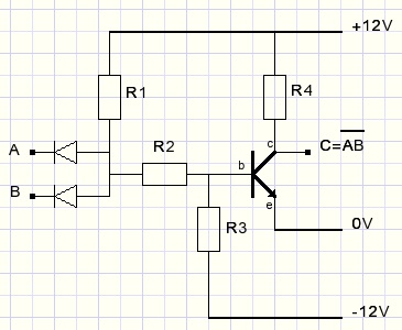
Only when voltage levels of A and B are both high, current flows through resistor R1,R2 into b to e of the transistor.
A transistor basically is a current amplifier. Normally there is a high resistance between c (collector) and e (emitter).
However, a small current from b (base) to e causes a much larger current to flow from c to e.
Amplification is somewhere between 20 and 100 typically.
The transistor therefore acts as a switch, being energized by a small current from b to e.
Current through resistor R4 and c,e of the transistor cause the output voltage to drop: a "0" level.
Therefore the circuit is a AND gate with inverter.
Note: A NAND gate may perform all necessary functions (AND,OR,NOT) to build a computer.
In realty however, computers are built using 2,3,4,8 input AND,NAND,OR,NOR gates and inverters.
To conclude this Boolean algebra introduction, AND,OR gates and inverter realised by NAND gates are shown.