

| DC networks program description |
The DC networks project
DC networks is written in the Delphi(7) programming language.It has the following forms and units:
form1 , unit1
form1 holds:-
- menu buttons
- a paintbox(1) for network drawing
- paintboxes showing components (wire, resistor, voltage source, ground contact)
- edit boxes to enter component values
- a label for messages
-
- procedures for program control
- event handlers
- paint procedures for the components
Final painting is done in bitmap map1.
While painting in map2 (by mousemovement) map1 is used to erase map2.
map2 is displayed in paintbox1.
Please refer to my other articles where drawing techniques are explained.
network_unit
This unit contains the data formats and procedures to define a networkand perform the calculation of currents and voltages.
resultform,result_unit
They hold a paintbox and procedures to display currents and voltages.I/O unit
Holds the open and save procedures to write and read networks from disc.debugform,debug_unit
A paintbox and procedures to display intermediate data (circuits and matrices).Also flags and a procedure to pause program execution.
Debugging needs code modification at design time.
It cannot be switched on by the user.
This description is limited to the network_unit
The network_unit
Data formats
const maxelement = 30;
      maxcontact = 60;
      maxEC      = maxElement + maxContact;

type TElementType = (etNone,etDelete,etWire,etResistor,etVoltage);//the components
     TS6 = string[6];
     TElement = record
                 elType  : TElementtype;
                 con1    : byte;         //nr of interconnection
                 con2    : byte;         //..
                 value   : double;       //Ohm, voltage
                 vtext   : TS6;          //as entered in edit box
                end;
     TContact = record
                 inUse : boolean;
                 x,y : smallInt;        //coordinate on screen
                end;
var element : array[1..maxelement] of Telement;
    elCount : byte;                    //number of elements in use
    contact : array[1..maxcontact] of TContact;
    groundContact : byte;              //number of ground contact
In an element current is supposed to flow from contact 1 to contact 2.(So a negative current flows from 2 to 1).
A new element is entered in the elements[ ] array at the top.
If an element is deleted, the elements positioned above are shifted down.
Variable elCount always points to the top of the elements list.
The contacts behave differently.
An entry in the contact[ ] array holds the boolean variable inUse indicating
that this contact is in use and positioned at (x,y).
If an element is deleted, it"s contacts may still be in use by other elements.
The groundcontact variable equals 0 if no ground is connected.
The registerElement procedure takes care of new elements or deletion of old elements:
function registerElement(var ep : TElement; x1,y1,x2,y2 : smallInt) : byte;the result is:
-
0 : element deleted
1 : element replaced
2 : registered OK
3 : max elements reached
4 : fake delete //delete symbol drawn but not matching existing element
Equation system to solve the currents
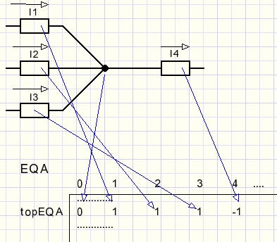
var EQA     : array[0..maxelement,1..maxEC] of double;//equation array
    topEQA  : byte;                                   //number of equations
A contact results in an equation such as I1 + I2 + I3 - I4 = 0The I1 value is entered in EQA[1, topEQA] := 1
The I4 value is entered in EQU[4, topEQA] := -1
The 0 value is entered in EQA[0, topEQA] := 0
Which elements are connected to a contact?
var ECV : array[1..maxcontact] of dword; //element-contact-vectorIf element 10 is connected to contact 5 then ECV[5] has bit 10 set.
.....
procedure makeEQA; //make equation array var i,j,n,nr : byte; mask : dword; mf : boolean; //modify flag ...... begin //make ECV : bit set for element connected to contact for j := 1 to maxcontact do ECV[j] := 0; for i := 1 to elCount do with element[i] do begin mask := 1 shl i; ECV[con1] := ECV[con1] or mask; ECV[con2] := ECV[con2] or mask; end;
ECV is used in procedure GetNextFreeElement, see later.
// Kirchhoff currents

 for j := 1 to maxContact do
  begin
   nr := topEQA + 1;
   mf := false;
   for i := 1 to elCount do      //Kirchhoff current
    with element[i] do
     begin
      if j = con1 then begin
                        EQA[i,nr] := 1;
                        mf := true;
                       end;
      if j = con2 then begin
                        EQA[i,nr] := -1;
                        mf := true;
                       end;
     end;//for i
    if mf then topEQA := nr;
  end;//for j
Well, this was the easy part.Next comes the implementation of Kirchhoff's current law.
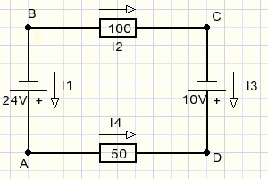
The path A...B...C...D...A is called a circuit.
Starting from A we use Ohm's law (E = I.R) to write the equation
-
-24 -100I2 +10 +50I4 = 0 ...........or
-100I2 + 50I4 = 14
-
I2 - I3 = 0
I3 + I4 = 0
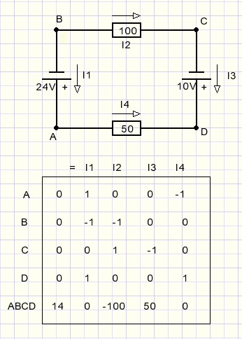
So, per element we have to find a circuit to apply Kirchhoff's voltage law.
Below I describe the method to find the shortest circuit for each element.
Finding circuits
Data structures:
type Tcircuit = record
                 ctIn,ctOut : byte;       //entry contact
                 el : byte;               //element
                 mult : shortInt;         //1, -1  multiplier
                end;

var circuit : array[1..maxContact] of Tcircuit;
    ccLength: byte;
    ECV     : array[1..maxcontact] of dword;  //element-contact-vector
    CEF     : array[1..maxcontact] of boolean;//contact enable flag
    EEF     : array[1..maxelement] of boolean;//element enable flag
    CCOK    : boolean;                        //circuit OK
The boolean array CEF[ ] enables contacts.A false flag prevents that the contact is selected (again).
Array EEF[ ] enables elements and prevent re-election of an element already part of a circuit.
The circuit array circuit[ ] holds the elements that make a circuit.
Variable mult (sign multiplier) equals 1 if ctIn = con1 and ctOut = con2.
mult = -1 if ctIn = con2 and ctOut = con1, when current flows reverse.
Remember that current is assumed to flow from element[ ].con1 to element[ ].con2 contacts.
One of the arrays CEF, EEF seems superfluous.
When searching for a circuit it is sufficient not to select contacts
that are already part of the circuit.
However, as the last contact in a circuit the starting contact must be choosen.
This contact should not be excluded. Elements may never appear twice in a circuit.
So I record both elements and contacts.
Following procedure is called when the analyse button is pressed:
procedure makeEQA;   //make equation array
var i,j,n,nr : byte;
    mlt  : shortInt; //sign multiplier for current direction
begin
......
// Kirchhoff voltages

 for i := 1 to elCount do     //for all elements
  begin
   ccLength := 0;             //reset circuit length
   if findCircuit(i) then     //if circuit found
    begin
     inc(topEQA);
     for j := 1 to ccLength do
      begin
       with circuit[j] do     //translate circuit data to equation
        begin
         n := el;
         mlt := mult;
        end;
       with element[n] do
        begin
         case eltype of
          etResistor : EQA[n,topEQA] := mlt*value;
          etVoltage  : EQA[0,topEQA] := EQA[0,topEQA] + mlt*value;
         end;//case
        end;
      end;//for j
    end;//if find..
  end;//for i
end;
MakeEQA calls findcircuit to.....(indeed).This function exits true if a circuit is found.
Parameter fel is the first element of the circuit.
Below I describe what is happening, see the listing for details.
function findcircuit(fel : byte)  : boolean;
//...a circuit made in array node[ ] is
//only stored in array circuit[ ] when it is shorter
var i : byte;
    node : array[1..maxElement] of TCircuit;
    nn,nel : byte; //node nr
label nextNode,nextMove;
begin
.....
//...preset CEF, EEF,Nodes
....
//...set first node (element, contacts)
.....
nextnode:
.....
//...increment node number nn
//   set ctIn to ctOut of previous node
.....
nextmove:
.....
//...if free element found
//      set element, contacts in node[ ]
//      if round trip
//         set result true
//         if shorter replace circuit[ ] by node[ ]
//      no round trip...goto nextNode
//.....
//...(move back to previous node)
//      re-enable element, contacts in EEF,ECF
//      remove node
//      goto nextMove
After finding a circuit, the last element is removed andcontrol is returned to the previous node
to find more (maybe shorter) circuits.
To find a free element:
function GetNextFreeElement(var el:byte; ct:byte) : boolean;
//get next free element connected to contact ct
//drop contact and element enables
var n,conOut : byte;
begin
 result := false;
 n := el;
 while (result = false) and (n < elCount) do
  begin
   inc(n);
   result := EEF[n] and (((1 shl n) and ECV[ct]) > 0);
   if result then
    with element[n] do
     begin
      if con1 = ct then conOut := con2 else conOut := con1;
      result := CEF[conOut];
     end;
  end;
 if result then
  with element[n] do
   begin
    EEF[n] := false;   //prevent using them again
    CEF[con1] := false;
    CEF[con2] := false;
    el := n;
   end;
end;
This concludes the construction of EQA, the equations array.Solving the equations in EQA
This is done by Gauss-Jordan elimination.A description is found [ here ].
Below a summary of the work:
procedure solveEQA;
var i,j,k,n,c1,c2 : byte;
    HV,M,D : double;
    nochange : boolean;
begin
...
//.....sweep columns down to zero
...
//.....sweep columns to zero from bottom to top
...
//At this point all entries in EQA[..,..] are zero except for EQA[i,i]
...
//.....divide rows to make diagonal all  = 1
...
//.....check for non zero values on diagonal (error check)
...
//.....if ground connected
//        make voltage list starting at groundcontact
This concludes the DC-networks project description.Please refer to the source code for details.

