

| Framework program description |
Framework is a program that tests frames for rigidity.
The frames are made of columns and rows of rectangular boxes.
This project is a nice application of graph theory
Introduction
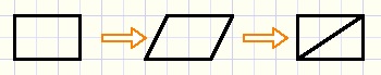
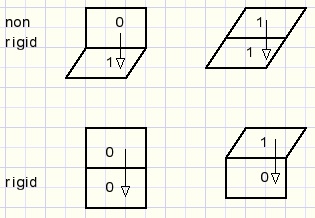
When force is applied to a rectangular box it may be distorted and become a parallellogram.However, if a brace is attached between opposite joints, the rectangle is now transformed
into two triangles and distortion is not possible.
See picture below:
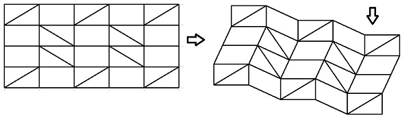
Using above boxes we may build frames of several rows and columns.
Then the question arises which boxes should be braced to make a rigid structure.
This framework project was built to answer this question.
If a frame is not rigid, the distortion is showed.
Also superfluous braces may be marked and removed to obtain a minimally braced rigid frame.
Below is a picture of the framework program at work.
Coding the problem
Columns and rows count 0..7 (maximum), left to right, top to bottom.Boxes are coded 0..3
-
box type 0 : vertical and horizontal edges. (binary code 00
box type 1 : rotated vertical edges. (binary code 01)
box type 2 : rotated horizontal edges. (binary code 10)
box type 3 : both edges rotated. (binary code 11)
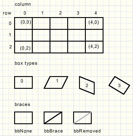
Per box the brace must be recorded.
bbRemoved indicates a removed brace, which was superfluous.
The frame is defined by it's coordinates (x,y).
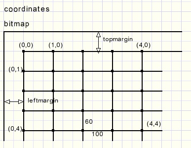
All drawing is done in a bitmap (map).
The map is displayed in a paintbox when drawing is finished.
This prevents drawing actions to cause flickering of the screen.
So, to display the frame distortion, simply the (x,y) coordinated have to be changed.
Here are the types, constants and variables needed for drawing:
type TBoxBrace = (bbNone,bbBrace,bbRemoved);

const leftmargin = 40;
      topmargin = 40;

var framewidth : byte; //1..8 number of boxes
    frameheight : byte;//1..8
    boxbrace : array[0..7,0..7] of TBoxBrace;
    coords : array[0..8,0..8] of TPoint; //coordinates of joints
    map : TBitmap;     //holds frame
The left-top (x,y) angle of a box is the reference.The other coordinates of the box angles depend on the box type and are relative to the left-top.
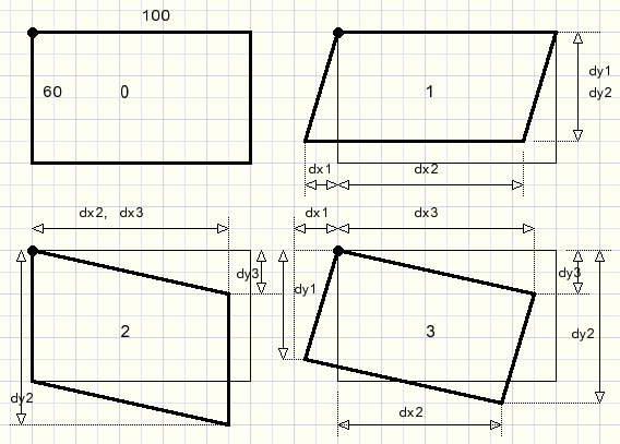
The dx-,dy- values are stored in a constants array[0..3] per box type 0..3:
const offset  : array[0..3] of TOffset =
  ((dx1:  0; dy1: 60; dx2: 100; dy2:  60; dx3: 100; dy3:  0), //0
   (dx1:-25; dy1: 54; dx2:  75; dy2:  54; dx3: 100; dy3:  0), //1
   (dx1:  0; dy1: 60; dx2:  91; dy2: 102; dx3:  91; dy3: 42), //2
   (dx1:-25; dy1: 54; dx2:  66; dy2:  96; dx3:  91; dy3: 42));//3
Above dx,dy values are calculated using basic goniometric functions.
Procedure testframe tests the frame and modifies the coordinates.
Procedure paintFrame paints the frame in the bitmap and copies the map to a paintbox.
Paintframe
Boxes are painted left to right, top to bottom.The box position is coded in variable code:
| 0 : left top | paint all edges |
| 1 : top row | paint top, right and bottom edges |
| 2 : left column | paint left , bottom and right edges |
| 3 : other | paint bottom and right edges |
Part of typical source code:
      case code of
       0 : begin                                     //left top
            moveto(coords[i,j].x, coords[i,j].y);
            lineto(coords[i+1,j].x, coords[i+1,j].y);
            lineto(coords[i+1,j+1].x, coords[i+1,j+1].y);
            lineto(coords[i,j+1].x, coords[i,j+1].Y);
            lineto(coords[i,j].x, coords[i,j].y);
           end;
      …......................
       2 : begin                                    //left
            moveto(coords[i+1,j].x, coords[i+1,j].y);
            lineto(coords[i+1,j+1].x, coords[i+1,j+1].y);
            lineto(coords[i,j+1].x, coords[i,j+1].Y);
            lineto(coords[i,j].x, coords[i,j].y);
           end;
       ….......................
      end;//case
For details please refer to procedure paintframe source code.So far for the painting. Now the harder part: testing the frame for rigidity.
Theory of rigid box testing
A box is called rigid if it cannot be distorted. It keeps straight angles.So these boxes are of type 0 or 3.
Of course a braced box is rigid.
But look at the next picture where the left-top box is not braced but sure is rigid:
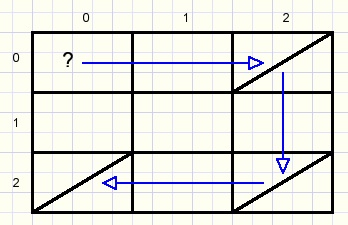
To examine box (0,0) for rigidity :
-
look for a brace in row 0 and find one in column 2.
now look for a brace in this column and find one in row 2.
next look for a brace in row 2 and find one in column 0.
If such a path from box(0,0) on row 0 to column 0 is not found
then box(0,0) is not rigid and will be a parallellogram, type 1 in this case.
Why is this true?
Looking back to previous pictures we notice that
-
in a row all left-right edges of the boxes are parallel.
In a column all top-bottom edges of the boxes are parallel
Box(2,0) and box(2,2) horizontal edges are parallel.
Because both boxes are braced also box(2,0) and box(2,2) vertical edges are parallel.
Same is true for box(2,2) and box(0,2).
So, boxes(2,2) and box(0,2) have parallel edges.
So, column 0 is perpendicular to row 0 and box(0,0) is a rectangle.
When is the complete frame rigid?
From the previous theory we conclude that it is sufficient to proof
that all boxes in row-0 and all boxes in column-0 are rigid.
The type of these top and left boxes fully determines the type of all other boxes.
Practice of rigid box testing
Function rigid(xcol,xrow : byte) : boolean; returns true if box(xcol,xrow) is rigid.This function is the core of the project.
These are the local variables:
var stepNr,n,v : byte;
    box        : array[1..16] of Tbox;
    colEnables : byte;
    rowEnables : byte;
    GO         : boolean;    //false to exit repeat loop
| stepNr | counts 1,2,3... as we step from row to column. StepNr 1 finds a brace in it's row, stepNr 2 a brace in it's column ...etc. |
| box[1..16] | search path of (x,y) coordinates |
| ColEnables rowEnables | start at value $ff [11111111] binary, enabling all rows/columns. If a column or row is part of the path, the corresponding bit is set to zero to avoid visiting this row/column again. This avoids loops in the path. |
| GO | a boolean flag for repeat loop exit control. |
Other variables defined outside this function are playing a role:
var columnvector : array[0..7] of byte;
    rowvector : array[0..7] of byte;
| columnvector, rowvector | bit coded brace positions in rows 0..7, columns 0..7 made by makeconnectionvectors from boxbrace[ ] array bit is set when brace is present |
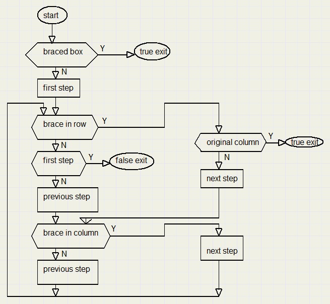
Function rigid has this little helper function:
function nextRect(var n : byte; vec : byte) : boolean;
//true if brace(bit) in vector vec; n : lowest bit set in vec
begin
 result := vec <> 0;
 if result  then
  begin
   n := 0;
   while ((1 shl n) and vec) = 0 do inc(n);
  end;
end;
byte vec has bits set for a brace in the column/row if this column/row
has not been visited before. Below is the flowchart of function rigid:
Frame testing
Testing the complete frame for rigidity is accomplished by procedure testframe.It is sufficient to test only the top row boxes by calling function rigid.
This procedure also changes the frame coordinates according to the box type found.
Variables:
var i,j : byte;  //column, row
    bxt : byte;  //box type etc.
    topbox : array[0..7] of byte; //top row box types
    leftbox : array[0..7] of byte;//left column box types
    xref,yref : smallInt;         //left-top box coordinates
    corr : smallInt;              //correction value, shift frame
    RFlag,CFlag : boolean;
The first test is for the left-top box. If rigid, the box type becomes 0, else the type is 1.Then the next box at (1,0) is tested. This box type depends on 1. rigidity and 2. the previous box(0,0).
For a rigid box, the next boxtype is precoded in constant topcodesR[0..3]
for a non-rigid box this is topcodesNR[0..3]
Example:
if box(0,0) is non-rigid (so type 1) and box (1,0) is rigid then box (1,0) is of type
topcodesR[1] which is type 3.
If box(0,0) is rigid and box (1,0) is non-rigid then box (1,0) is of type topcodesNR[0] = 2.
The previous boxtype is the index into these constant arrays.
Next picture lists the top box choices:
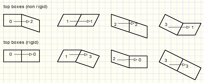
So far the top boxes.
At this point the bottom and top edge directions of all boxes are fixed.
This means that the left- and right edges in a row are also fixed if this row contains a braced box.
Testing continues with the left column box (0,1), just below the top-left box.
If this row has a braced box, boolean variable Cflag sets true.
Source code (without code for coordinates change):
   CFlag := nextRect(bxt,rowvector[j]); //braced box in row?
   if CFlag then
    begin
     bxt := topbox[bxt];
     bxt := ((bxt and $2) shr 1) or (leftbox[0] and $2);
    end
    else bxt := 1;
The vertical edge is derived from the topbox horizontal direction and the horizontal edgeis the left-top horizontal edge direction.
Left column successor box types:
For boxes not at the top row or the left column, this code does the job:
 for j := 1 to frameheight-1 do    //not top or left
  for i := 1 to framewidth-1 do
   begin
    xref := coords[i,j].x;
    yref := coords[i,j].y;
    bxt := (leftbox[j] and $1) or (topbox[i] and $2);
    coords[i+1,j+1].x := xref + offset[bxt].dx2;
    coords[i+1,j+1].y := yref + offset[bxt].dy2;
   end;
The horizontal bit comes from the top box, the vertical bit from the left box.Afterward the frame is shifted horizontally by value corr to maintain a left margin.
Saving and loading
Frames may be saved / loaded to/from disc.The data format allows for future expansion to frames of 32 * 32 columns/rows maximum.
Data I/O is typed. Files have no extension.
The data pack consists of 37 dwords (cardinals)
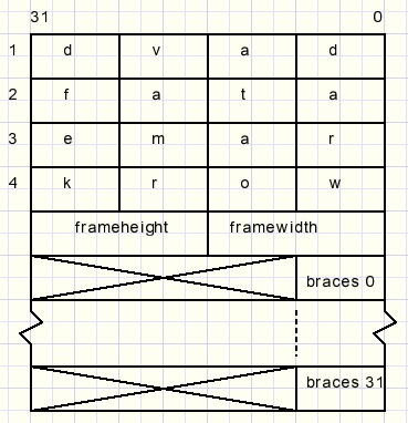
The pack starts with text “davdataframework” for identification.
Braced fields have a bit set for a brace in the row.
Please refer to the source code for more details.
Postscript
This problem was found in the book “Graphs, an introductory Approach” by Wilson and Watkins.A graph in mathematics is a drawing of points which may, or may not, be connected by lines.
Such a drawing is abstract and may represent topics like:
-
road maps
networks
chemical molecules
interdependent processes
where points belong to one of two groups and lines connect a point in one group to a point in the other group.
Also graphs may have several properties one being connected.
This means that travel from a point to any other point is possible over the connecting lines.
The frame problem may be represented by a bipartite graph by assigning a point
in group 1 for each column and a point in group 2 for each row.
A connecting line shows that the column / row is braced.
The frame is rigid if the graph is connected.
See examples below:
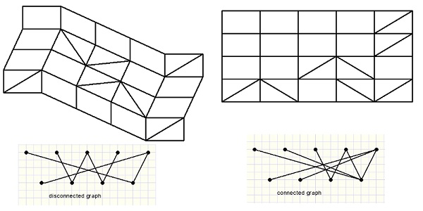
The top row of points represent the columns (0,1,2,3,4).
The bottom points are the rows (0,1,2,3) of the frame.

