| the Hbot |
De Hbot robot is called after it's H shape.
This robot performs 2 dimensional movements so, in the X and Y direction.
Special in this design is the single (timing) belt and the two motors.
These motors are fixed mounted, they do not move.
In this article I explain the Hbot operations.
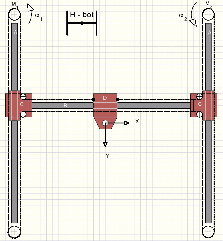
Please look at the picture above.
M1 and M2 are stepper motors. Their rotation is electronically controlled.
(rotation angles expressed in radians)
If a motor rotates over a degrees the timing belt moves a distance ar
where r is the radius of the motor pulley.
B is a horizontal guide bar.
D moves horizontally over B.
B and C make a fixed construction which moves vertically over guide bars A.
The timing belt has both ends connected to D.
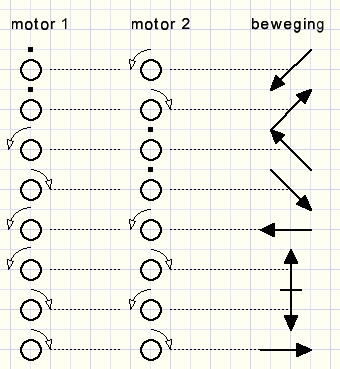
Horizontal, vertical and diagonal movement results when the motors
turn left, right or halt.
Case 1
Motor 1 rotates left, motor 2 halts.
Please look at at the schematical picture below:
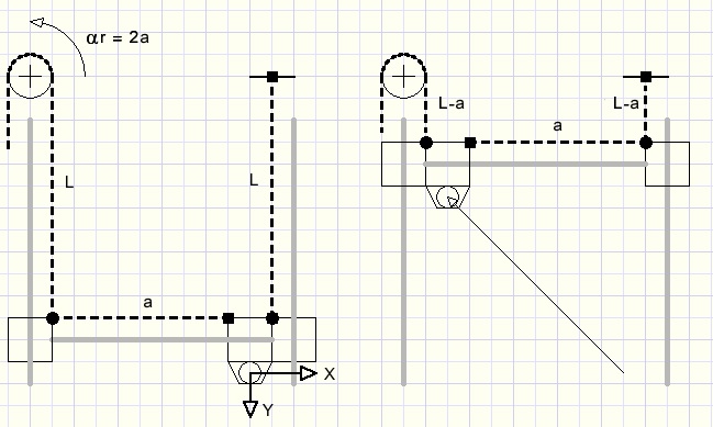
Left the belt length is L + a + L = 2L + a.
Right the belt length is L-a + L-a + a = 2L - a.
The left motor (1) has moved the belt over a distance of 2a.
Movement over length a therefore results in a robot (pen) movement of 0.5a in both
horizontal and vertical direction:
-
x = -0,5a
y = -0,5a
Case 2
Motor 2 rotates left and moves the belt over distance a, motor 1 halts.
We assume the robot (pen) at position (0,0) at the right top.
Similar with the above case we notice:
-
x = -0,5a
y = 0,5a
Motor 1 turns left, motor 2 turns left.
Both motors move the belt over distance a.
The result is the addition of cases 1. and 2.
-
x = -0,5a - 0,5a = -a
y = -0,5a + 0,5a = 0
Case 4
Motor 1 turns left, motor 2 turns right.
Motor 2 moves the belt over distance -a.
Addition:
-
x = -0,5a + 0,5a = 0
y = -0,5a -0,5a = -a
Summary
("beweging" is Dutch for "movement")