

| Programming a rotating globe |
Downloads
There are two Delphi-7 projects:-
globe 1: small globe with programming explanation below.
globe 2: large globe, to be rotated.
| download program 1 | download complete Delphi project 1 | ||||
| download program 2 | download complete Delphi project 2 |
Introduction
 |
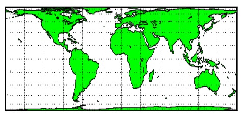 |
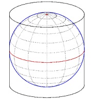
Then walking the globe from north to south, the pixels are recorded on vertical lines on the cilinder.
Then the cilinder is unwrapped.
The width of the projection rectangle equals p x globe diameter.
The height is half of that value.
At the equator, the pixel size matches the pixels on the globe,
but in the projection the pixels at higher or lower latitudes become more stretched horizontally.
Also, this Delphi programming project includes globe rotation.
The time required to build the globe from the rectangular projection is 3 milliseconds.
This project uses fixed dimensions of globe and projection image.
For a much larger globe a new project was build, but this is not discussed here.
How it works
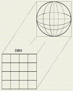
First a 1:1 rectangle is selected from the 2:1 globe image map.Rotation is realized by selecting different parts.
This selection is placed in a bitmap SBM (source bitmap).
The globe is constructed in bitmap DBM (destination bitmap).
The pixels of DBM are scanned from left to right, from top to bottom.
A previously (at create time) calculated table (CCT, coordinate conversion table)
provides a rectangular area on bitmap SBM for each DBM pixel.
The pixel colors in this area are summed and the average value is taken.
This color is then stored in the DBM pixel.
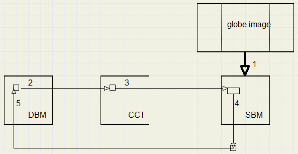
Other quadrant values are derived from the reflexion on the horizontal and vertical centerlines.
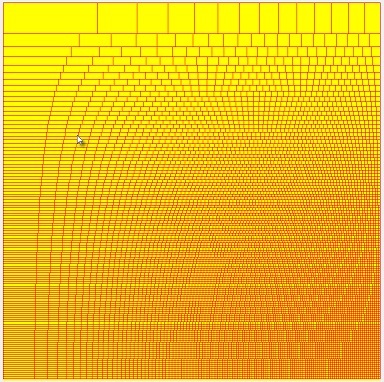
Below is a picture of the CCT values on SBM.
Making the CCT (coordinate conversion table)
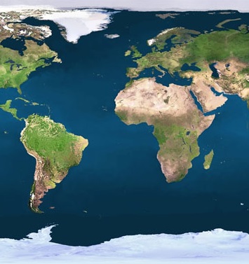
The source image has dimensions 756 x 378 pixels.The SBM has 378 x 378 pixels.
The pixels were taken from arcs on the sphere, so the sphere originally had a diameter of
756 / p = 240.6 pixels.
We choose a destination bitmap with a diameter of 240 pixels.
The CCT therefore has dimensions 120 x 120 pixels, the left-top quarter.
Note, that the project is written for these fixed values only.
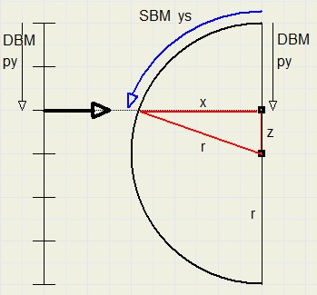
First, we relate the vertical coordinate of a DBM pixel to the SBM .
The vertical coordinate on SBM is ys.
They are named differently in the project.
For a certain py value in the DBM, we calculate
z = r � py.
X = sqrt(r^2 � z ^2)
ys = r . arctan(x / z)
Remember, that the arctan function produces an angle in radians.
Then, for an angle, the arc on a circle is simply obtained by multiplying
the angle by the radius. ( 2p radians = 360 degrees)
Of course, the final ys value must be rounded to integer because it is the SBM y coordinate.
Next we have to calculate the horizontal coordinate xs on the SBM bitmap.
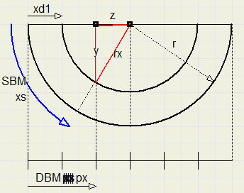
z = r � px
rx = r � xd1 ( xd1 = 120 � x , see picture of sy calculation)
y = sqrt(rx^2 � z^2)
xs = r . arctan(y / z)
Again, xs must be rounded to integer.
The concludes the theory.
Rectangles on SBM can be formed by taking subsequent values of (xs,ys) from the CCT.
Color handling.
Taking single pixels from SBM will result in coarse pictures.This may be avoided by calculating in floating point values however here we seek a compromise.
A pixel is supposed to exist of 16 subpixels, 4 columns and 4 rows.
This is simply obtained by multiplying the pixel cordinates by 4,
which is done by a left shift of 2.
The lower 2 bits with values 0,1,2,3 then select the subpixel.
In this case we produce enough accuracy for fluent colors and avoid slower floating point arithmetic.
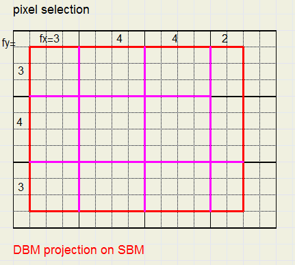
Cf = fx . fy is the number of quarter pixels selected.
These numbers are summed in variable cfs = cfs + cf.
The pixel colors are summed in variables colR, colG, colB for red, green, blue respectivily.
ColR = colR + cf . PixelColor etc.
The final average red color = ColR / cfs.
Color extraction from a pixel.
Windows has this internal format to store a color: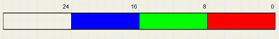
The most convenient format is pf32bit (pixelformat property) which is:
To speed up operations we do not use the bitmap property pixels[ . ] .
Instead we directly read and write pixels in memory which is 50 times faster.
A bitmap has property scanline[n] which supplies the memory address of the leftmost pixel of line n.
This address is stored as a dword ( = cardinal) variable to enable calculations.
For bitmap DBM two values are calculated:
1: DBM0 = dword(DBM.scanline[0]
2: DBMstep = DBM0 � DBM.scanline[1]
Also a data type P32 is defined:
type P32 = ^dword;
Similar, for bitmap SBM, SBM0 and SBMstep are calculated.
To read the pixel[x,y] value into a variable color :
addr := SBM0 � y*SBMstep + (x shl 2)
color := P32(addr)^
To extract the color fields from color:
colR := color shr 16; //red
colG := (color shr 8) and $ff; //green
colB := color and $ff; //blue
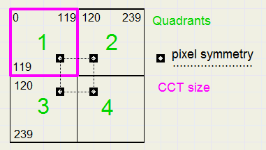
Quadrants
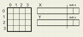
The CCT has size 120 * 120 pixels.The DBM has four quadrants, 1..4.
Procedure MakeSphere
The general layout, many loops within loops:---------------------------------------------------------------------
by steps 1..119 through pixel rows of DBM (by: base y value)------------------------------------------------------------------
bx steps xd1..119 through pixel columns of DBM
{ (hx1,hy1)..(hx2,hy2) define SBM rectangle (hx = home value x)}
q counts 1..4 to select quadrants
{(px,py) are calculated from (bx,by) to address DBM} {(x1,y1) and (x2,y2) are calculated from (hx1,hy1) (hx2,hy2) to address SBM quarterpixels} {(sx1,sy1) , (sx2,sy2) are true pixels positions on SBM} j counts sy1 .. sy2 on SBM i counts sx1 to sx2 on SBM {collect pixelvalues in colR, colG, colB} end of j,i loops {calculate color value and save in (px,py)} end of q loop end of bx loop end of by loop
Information for debugging
Programming is making mistakes continuously.So it is of great help to check procedings step-by-step.
When we look at the globe we observe a circle.
Pixels outside this circle do not need to be processed.
How to draw a nice circle?
The circle we created is pictured in paintbox3 (dimensions 240 * 240)
Below I show paintbox3 somewhat enlarged:
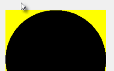
Note, that the upper line is not used to avoid a single pixel.
for i := 1 to 119 do
 with CCT[i] do
  begin
   r := sqrt(14400-sqr(i-120));
   xd1 := round(120-r);
  end;//for i
xd1 is the leftmost circle pixel for line i.
14400 is the square of 120, the radius of the circle.
We recognize the Pythagoras lemma.
In painbox2 on form1, the layout of the CCT is painted. See picture before.
Each rectangle holds the bits that must be summed to produce one destination pixel.
type TCC  = record
             xd1 : smallInt;     // x start on dest map
             ys  : smallInt;     // y position on source *4
             xs  : array[0..119] of smallInt; //x position *4
            end;

var sbm,dbm : Tbitmap;
    CCT : array[0..119] of TCC;
    HRpos : smallInt;        //horizontal center on source map
    dbm0,sbm0 : dword;       //location of [0.0]
    dbmstep,sbmstep : dword; //step down to next line
When moving the mouse over paintbox2,the corresponding information of the CCT is displayed in statictext components.
Rotation
Bitmap SBM is formed from image1 in the following way:
procedure buildSbm;
//build source bitmap from globe image
//use HRpos to select part of image = 756 * 378
var r,s : TRect;
begin
 with form1.image1.Picture.bitmap do
  begin
   s.Top := 0; s.Bottom := 378; r.Top := 0; r.Bottom := 378;
   if HRpos <= 378 then
    begin
     s.Left := Hrpos; s.Right := s.Left + 378;
     r.Left := 0; r.Right := 378;
     sbm.Canvas.CopyRect(r,canvas,s);
    end
    else
     begin
      s.Left := Hrpos; s.Right := 756;
      r.left := 0; r.Right := 756-HRpos;
      sbm.Canvas.CopyRect(r,canvas,s);
      r.left := r.Right; r.Right := 378;
      s.Left := 0; s.Right := HRpos-378;
      sbm.Canvas.copyrect(r,canvas,s);
     end;
  end;
end;
If the selection of the image overflows an edge then two copies are neededfrom the image to SBM to assemble the correct parts of the globe.
Copy takes place from rectangle s om the image to r on SBM.
The most difficult part of the program is the calculation of the CCT.
Some magic numbers may appear in this code but remember that we basically
calculate angles in radians and multiply them with the sphere radius to get the lengths of the arc.
Also these values are multiplied by four to address subpixels.
This is a good moment to conclude the description.
For more details I refer to the source code.
Picture below finally shows the SBM left and DBM right.
 |
 |

